cnc machine circuit diagram pdf Creating a CNC wiring diagram requires a good understanding of electrical circuits and the specific requirements of your CNC machine. It is recommended to consult the documentation provided with your CNC machine kit or seek .
If you have enough available amperage for the circuits you intend to add, a subpanel is easier since you don't have to upgrade your main circuit breaker. There are specific rules you have to follow when installing a subpanel, particularly the ground and neutral bars MUST be isolated from each other.
0 · parts made by cnc machine
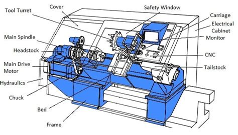
1 · main parts of cnc machine
2 · cnc machining process flow chart
3 · cnc machine labelled diagram
4 · cnc machine drawing PDF
5 · block diagram of nc machine
6 · block diagram of cnc machine
7 · basic elements of cnc machine
national fabricator of EQUITONE fiber cement, Trespa phenolic resin and ALPOLIC metal composite panel systems for architectural aesthetics fascia / facade design elements. Metal Composite - Universe Facade Solutions - architectural aesthetics cladding fascia
This document provides a diagram of the wiring for a 5 axis CNC machine. It shows the power supply and distribution, as well as the wiring between the breakout board, driver boards, stepper motors and computer interface. A CNC machine circuit diagram is a visual representation of the electrical circuits necessary to power and control a CNC machine. It’s a schematic that outlines the connections between the electronic components of the .Second monitor could be set to stop machine if maximum rpm-while-doors-open is exceeded. Safety Relay Door Interlocks: Controlled by door interlock contacts. . FANUC WIRING .block diagram. d. es0121. nts. 5. machmotion 14518 cr 7240 rolla, missouri, usa 573-368-7399 machmotion.com. operator pc. note: all functions may not be present or available as shown. .
View and Download CNC 3018-PRO user manual online. 3018-PRO industrial equipment pdf manual download.Creating a CNC wiring diagram requires a good understanding of electrical circuits and the specific requirements of your CNC machine. It is recommended to consult the documentation provided with your CNC machine kit or seek .
Switches, contactors and PSUs represented in this diagram are used for illustration purposes only. Please select appropriate components based on your build and power source (110V or .With this 5 axis breakout board, any 1-5 single axis stepper driver controllers can be directly controlled by the PC via the MACH3, Compatible with MACH3, Linux CNC (EMC2) etc. .Wiring diagrams shown below are for 4-axis (5 motor drivers) systems. A CNC machine wiring diagram is a documented blueprint detailing the electrical connections necessary to power a CNC machine. The diagram typically includes a connection point map with detailed diagrams of the .
This document provides a diagram of the wiring for a 5 axis CNC machine. It shows the power supply and distribution, as well as the wiring between the breakout board, driver boards, stepper motors and computer interface. A CNC machine circuit diagram is a visual representation of the electrical circuits necessary to power and control a CNC machine. It’s a schematic that outlines the connections between the electronic components of the machine, such as motors, sensors, and encoders.Second monitor could be set to stop machine if maximum rpm-while-doors-open is exceeded. Safety Relay Door Interlocks: Controlled by door interlock contacts. . FANUC WIRING DIAGRAM 5.11 E350_DRIVES CNC CONTROL WIRING DETAIL. SEPTEMBER 2005 18 of 38 FADAL MACHINING CENTERS 5.12 E400_SPINDLE AMP DRIVE WIRING DETAIL WYE .block diagram. d. es0121. nts. 5. machmotion 14518 cr 7240 rolla, missouri, usa 573-368-7399 machmotion.com. operator pc. note: all functions may not be present or available as shown. refer to user manual. motion controller spindle drive axis drive axis drive axis drive internet ethernet #1 spindle control cable axis encoder cables note .
View and Download CNC 3018-PRO user manual online. 3018-PRO industrial equipment pdf manual download.
parts made by cnc machine

main parts of cnc machine
Creating a CNC wiring diagram requires a good understanding of electrical circuits and the specific requirements of your CNC machine. It is recommended to consult the documentation provided with your CNC machine kit or seek professional advice to ensure accurate wiring.Switches, contactors and PSUs represented in this diagram are used for illustration purposes only. Please select appropriate components based on your build and power source (110V or 220V, 15A or 20A or 30A).

With this 5 axis breakout board, any 1-5 single axis stepper driver controllers can be directly controlled by the PC via the MACH3, Compatible with MACH3, Linux CNC (EMC2) etc. parallel-control CNC software. USB power supply and peripherals powered phase are separated to protect computer security.
Wiring diagrams shown below are for 4-axis (5 motor drivers) systems. A CNC machine wiring diagram is a documented blueprint detailing the electrical connections necessary to power a CNC machine. The diagram typically includes a connection point map with detailed diagrams of the different cables .This document provides a diagram of the wiring for a 5 axis CNC machine. It shows the power supply and distribution, as well as the wiring between the breakout board, driver boards, stepper motors and computer interface.
A CNC machine circuit diagram is a visual representation of the electrical circuits necessary to power and control a CNC machine. It’s a schematic that outlines the connections between the electronic components of the machine, such as motors, sensors, and encoders.Second monitor could be set to stop machine if maximum rpm-while-doors-open is exceeded. Safety Relay Door Interlocks: Controlled by door interlock contacts. . FANUC WIRING DIAGRAM 5.11 E350_DRIVES CNC CONTROL WIRING DETAIL. SEPTEMBER 2005 18 of 38 FADAL MACHINING CENTERS 5.12 E400_SPINDLE AMP DRIVE WIRING DETAIL WYE .block diagram. d. es0121. nts. 5. machmotion 14518 cr 7240 rolla, missouri, usa 573-368-7399 machmotion.com. operator pc. note: all functions may not be present or available as shown. refer to user manual. motion controller spindle drive axis drive axis drive axis drive internet ethernet #1 spindle control cable axis encoder cables note .
View and Download CNC 3018-PRO user manual online. 3018-PRO industrial equipment pdf manual download.Creating a CNC wiring diagram requires a good understanding of electrical circuits and the specific requirements of your CNC machine. It is recommended to consult the documentation provided with your CNC machine kit or seek professional advice to ensure accurate wiring.Switches, contactors and PSUs represented in this diagram are used for illustration purposes only. Please select appropriate components based on your build and power source (110V or 220V, 15A or 20A or 30A).
With this 5 axis breakout board, any 1-5 single axis stepper driver controllers can be directly controlled by the PC via the MACH3, Compatible with MACH3, Linux CNC (EMC2) etc. parallel-control CNC software. USB power supply and peripherals powered phase are separated to protect computer security.Wiring diagrams shown below are for 4-axis (5 motor drivers) systems.

cnc machining process flow chart

retrofit electrical outlet box
Single Door, Single Lock Narcotic Cabinet with One Shelf. Model 7782. UMF Medical’s 7782 Narcotic Locker is manufactured with 20-gauge steel, offering a single door, single lock and one shelf. 14.125" (Wide) x 12" (High) x 8.125" (Deep)
cnc machine circuit diagram pdf|cnc machine drawing PDF