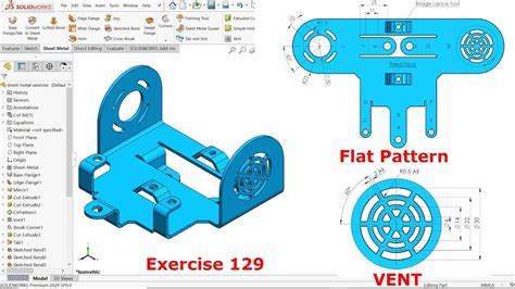
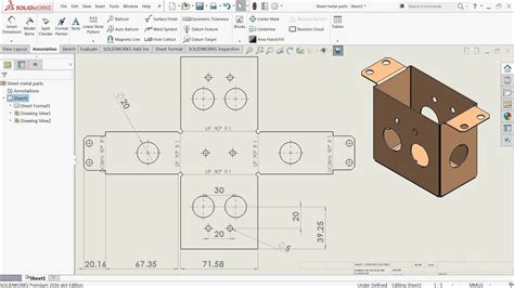
drawing sheet metal parts Reading a sheet metal drawing involves identifying the details of the design of sheet metal parts, such as dimensions, geometry, material specifications, and any special requirements. Meanwhile, detailing this . Elite Welding & Fabrication has over 20 years of combined fabrication and welding service. We offer mig and tig welding, CNC cutting and forming, and 3D CAD support, along with many other services.
0 · solidworks sheet metal drawings
1 · simple sheet metal drawings
2 · sheet metal layout drawings
3 · sheet metal drawings with gd&t
4 · sheet metal command in solidworks
5 · sheet metal basic drawing
6 · sheet metal 3d sketch solidworks
7 · metal sheet riveted together drawing
One-stop shop for custom metal fabrication, design assistance, and optimization. We specialize in working with small to medium-sized ODMs and OEMs. 513-554-1022
Sheet metal drawings are a type of mechanical drawing primarily used to depict the details and dimensional specifications of sheet metal fabrication parts. They provide detailed descriptions of the part’s shape, . Reading a sheet metal drawing involves identifying the details of the design of sheet metal parts, such as dimensions, geometry, material specifications, and any special requirements. Meanwhile, detailing this . This article endeavors to demystify the intricate domain of sheet metal drawing, focusing specifically on its more specialized variant, deep drawing. We’ll delve into its foundational principles, the technical aspects, and myriad . There are two types to choose from, sheet metal and part features: Although many features between the two are similar, it is preferred that you use all sheet metal features if .
Accuracy in sheet metal drawings is paramount as it directly impacts the quality, fit, and functionality of fabricated components. Precise dimensions, tolerances, and material specifications ensure that parts align . Follow these best practices next time you create a sheet metal fabrication drawing to help your shop turn the project around quickly: 1. List part numbers, not just the part name. Part names are great, but it’s helpful to .
In sheet metal fabrication, having a solid grasp of CAD (Computer-Aided Design) drafting and modeling is essential for achieving top-tier product quality and operational efficiency. We demonstrate how to create detailed Sheet Metal Drawings & DXFs of different configurations using multi-body parts in SOLIDWORKS & more.
solidworks sheet metal drawings

In this article, we’ll discuss how you can make sure you create technically correct and more manufacturable sheet metal drawings. The most important general considerations to make in design are precision in terms of .A fully dimensioned sheet metal drawing includes dimensions for all bends, holes, countersinks, flanges, and other formed features (such as hems and curls, ribs, dimples, etc.). It is a best practice to dimension to virtual intersection points and show included bend angles. Sheet metal drawings are a type of mechanical drawing primarily used to depict the details and dimensional specifications of sheet metal fabrication parts. They provide detailed descriptions of the part’s shape, dimensions, material, surface treatments, allowable tolerances, and other pertinent information.
Reading a sheet metal drawing involves identifying the details of the design of sheet metal parts, such as dimensions, geometry, material specifications, and any special requirements. Meanwhile, detailing this information requires a series of .
This article endeavors to demystify the intricate domain of sheet metal drawing, focusing specifically on its more specialized variant, deep drawing. We’ll delve into its foundational principles, the technical aspects, and myriad benefits. There are two types to choose from, sheet metal and part features: Although many features between the two are similar, it is preferred that you use all sheet metal features if possible. Accuracy in sheet metal drawings is paramount as it directly impacts the quality, fit, and functionality of fabricated components. Precise dimensions, tolerances, and material specifications ensure that parts align correctly, preventing costly errors in manufacturing. Follow these best practices next time you create a sheet metal fabrication drawing to help your shop turn the project around quickly: 1. List part numbers, not just the part name. Part names are great, but it’s helpful to provide part numbers, too.
In sheet metal fabrication, having a solid grasp of CAD (Computer-Aided Design) drafting and modeling is essential for achieving top-tier product quality and operational efficiency. We demonstrate how to create detailed Sheet Metal Drawings & DXFs of different configurations using multi-body parts in SOLIDWORKS & more. In this article, we’ll discuss how you can make sure you create technically correct and more manufacturable sheet metal drawings. The most important general considerations to make in design are precision in terms of product design and the need to design for manufacturability.
A fully dimensioned sheet metal drawing includes dimensions for all bends, holes, countersinks, flanges, and other formed features (such as hems and curls, ribs, dimples, etc.). It is a best practice to dimension to virtual intersection points and show included bend angles. Sheet metal drawings are a type of mechanical drawing primarily used to depict the details and dimensional specifications of sheet metal fabrication parts. They provide detailed descriptions of the part’s shape, dimensions, material, surface treatments, allowable tolerances, and other pertinent information. Reading a sheet metal drawing involves identifying the details of the design of sheet metal parts, such as dimensions, geometry, material specifications, and any special requirements. Meanwhile, detailing this information requires a series of .
This article endeavors to demystify the intricate domain of sheet metal drawing, focusing specifically on its more specialized variant, deep drawing. We’ll delve into its foundational principles, the technical aspects, and myriad benefits.
There are two types to choose from, sheet metal and part features: Although many features between the two are similar, it is preferred that you use all sheet metal features if possible.
Accuracy in sheet metal drawings is paramount as it directly impacts the quality, fit, and functionality of fabricated components. Precise dimensions, tolerances, and material specifications ensure that parts align correctly, preventing costly errors in manufacturing. Follow these best practices next time you create a sheet metal fabrication drawing to help your shop turn the project around quickly: 1. List part numbers, not just the part name. Part names are great, but it’s helpful to provide part numbers, too.In sheet metal fabrication, having a solid grasp of CAD (Computer-Aided Design) drafting and modeling is essential for achieving top-tier product quality and operational efficiency.
We demonstrate how to create detailed Sheet Metal Drawings & DXFs of different configurations using multi-body parts in SOLIDWORKS & more.
simple sheet metal drawings

stainless steel wire mesh box
sheet metal layout drawings
Welding and Metal Fabrication Book pdf by Larry Jeffus. Welding and Metal Fabrication is designed to help you develop all of the skills to become a highly-paid paid versatile welder.
drawing sheet metal parts|metal sheet riveted together drawing